Wiring Towmaster Trailers
6.5 4S/2M Trailer ABS Configuration Diagram for LiftAxle Applications (Forward Lift Axle Installation Diagram). 29. and illustrates ABS components and wiring and plumbing installation diagrams. This manual does not contain Original Equipment Manufacturer (OEM) installation instructions. New installations require the following documentation:
Semi Trailer Abs Wiring Diagram Wiring Diagram
ABS Controller Step 1 What equipment does the trailer have? Record the total of checked boxes: ______ Wheel Speed Sensors (WSSs), ______ Modulator Valves (MVs). Step 2 What Blink Code (BC) numbers are shown as active or intermittent? We recommend that you use a PC/laptop with associated RP1210 harnesses, etc. to connect to the trailer.

wabco trailer abs wiring diagram TrenaHaziim
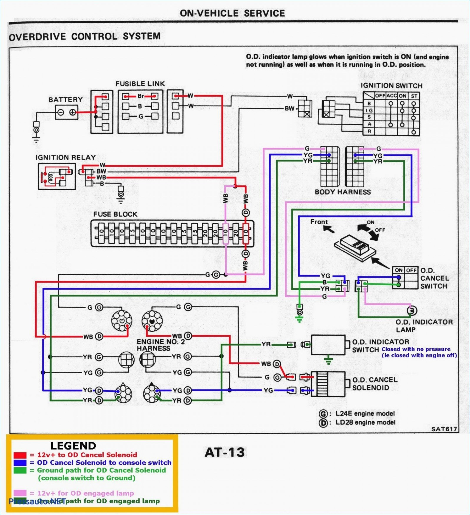
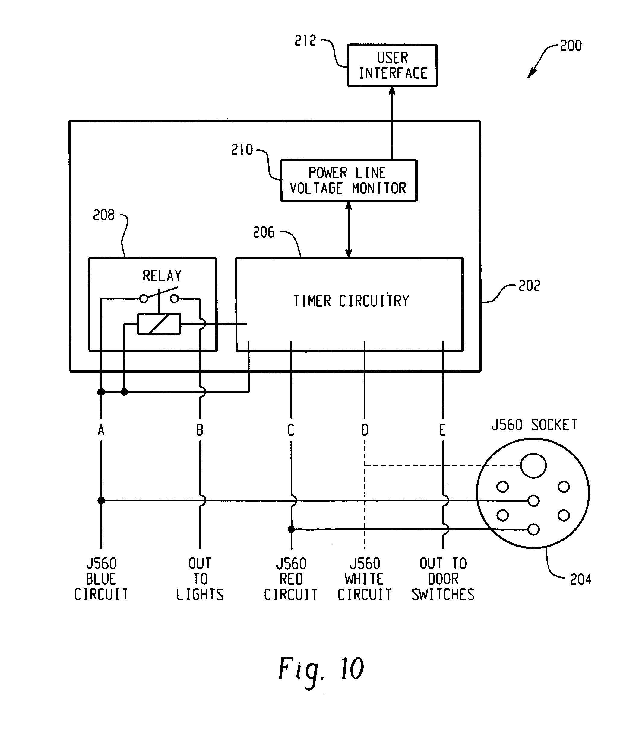
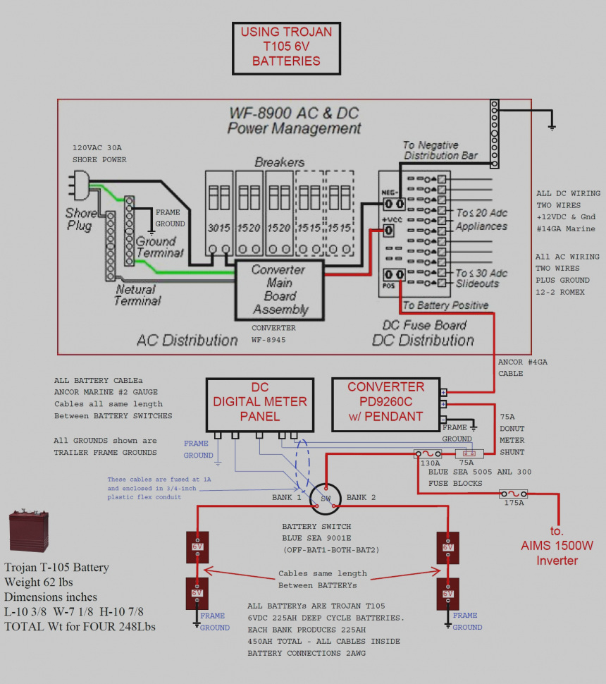
Page 1 iABS™ TRAILER ABS SYSTEM WITH PLC AND CAN 2S/1M, 2S/2M, 4S/2M AND 4S/3M STANDARD/PREMIUM MAINTENANCE MANUAL MM19001. Page 29 System Confi gurations 5.2 Power Cable Wiring Diagrams Fig. 5.9 WHITE (GROUND) BLUE (CONSTANT POWER) (STOP LAMP).

Wabco Trailer Abs Wiring Diagram
Haldex Trailer Abs Wiring Diagram ABS Troubleshooting for Trucks, Trailers, and Buses. STEP 4: Fault Codes for Haldex ABS Modal ECU. Use the table to identify ABS faults from the ECU Fault. ABS Troubleshooting for Trucks, Trailers, and Buses. STEP 3: Blink code identification and system response. If you already know how to read ABS Blink Codes.

Wabco Trailer Abs Wiring Diagram General Wiring Diagram
DELIVERY CURBSIDE one unit. The LED on top of the ECU has been eliminated. The blink code tool LED does not operate simultaneously with the ABS lamp on the trailer. For Enhanced Easy-StopTM 4S/3M lift axle installations, you must use TOOLBOXTM Software, version 4.6 or higher, to enable the lift axle function. It is not automatically enabled.

Haldex Trailer Abs Wiring Diagram
All modules include an Electronic. Control Unit (ECU) and Modulator Relay Valve (MRV) which are. integrated into a single self-contained 2S/1M (two-sensor, one. modulator) trailer ABS unit. The Premium TABS-6 module is. auto-configurable to control more sensors and modulators (up to. 4S/3M) from its default 2S/1M.
Wabco Trailer Abs Wiring Diagram Wiring Diagram
Trailer Retrofit Solutions Enhanced Easy-Stop™ Trailer ABS Trailer ABS Truck and Bus Air Supply and Processing Governor and Unloader System Saver 1200 & 1800 System Saver Twin Air Dryer System Saver 1200Plus and HP Electronically Controlled Air Dryer Filtering Products Coalescing Cartridge Standard Cartridge Air Storage Drain valve
Trailer Abs Wiring Diagrams Manual EBooks Wabco Trailer Abs Wiring
The ABS indicator lamp will be on 2. Turn the ignition switch off. The ABS indicator lamp will go out 3. Turn the ignition switch on. The ABS indicator lamp will then come on, then go out 4. The blink code will be displayed by the ABS indicator lamp on the trailer 3. If blink code is 7 (ABS lamp flashes 7 times), the issue could be related to.

Wabco Trailer Abs Wiring Diagram Best Of Air brake, Abs brake system
A trailer's ABS system, also known as its antilock braking system, is a critical component of any trailer setup. It is responsible for providing a stable platform for the trailer and its occupants during braking, and can be the difference between a safe and an unsafe journey.

13+ wabco trailer abs wiring diagram FerdavsAlaa
The Wabco Trailer ABS Wiring Diagram can be used as a reference guide when installing or repairing the ABS system. It helps technicians identify and isolate any potential issues with the wiring, such as loose connections, damaged wires, or faulty components. By following the diagram, technicians can ensure that the ABS system is properly.

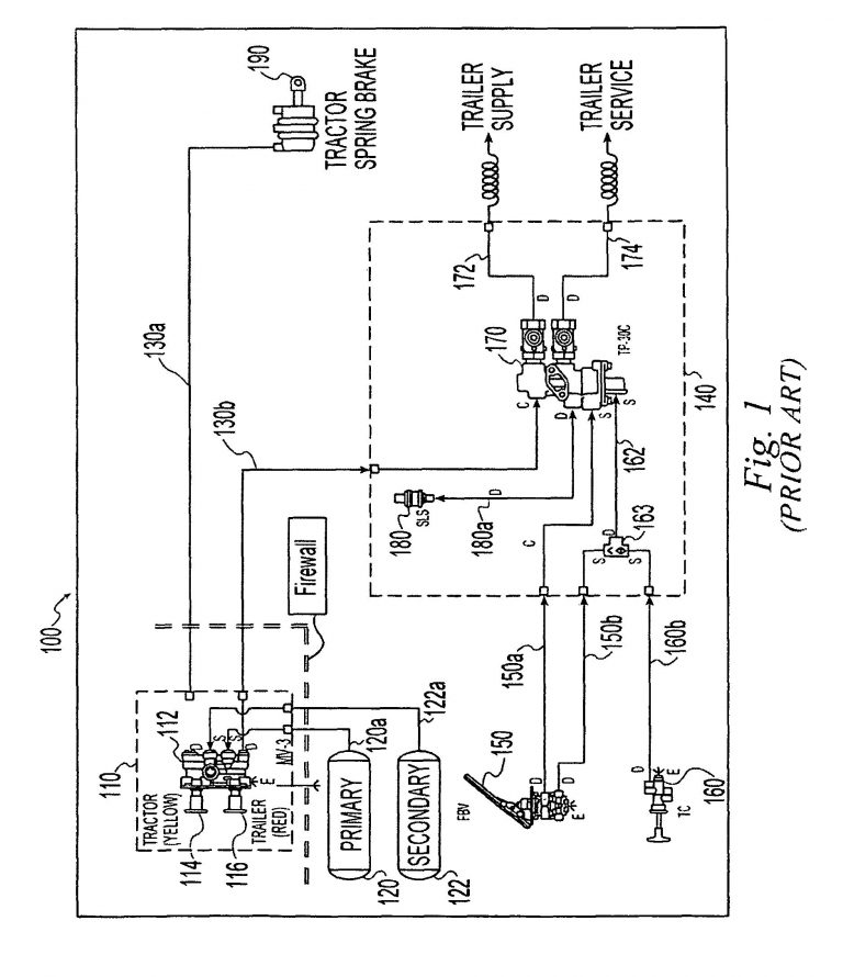
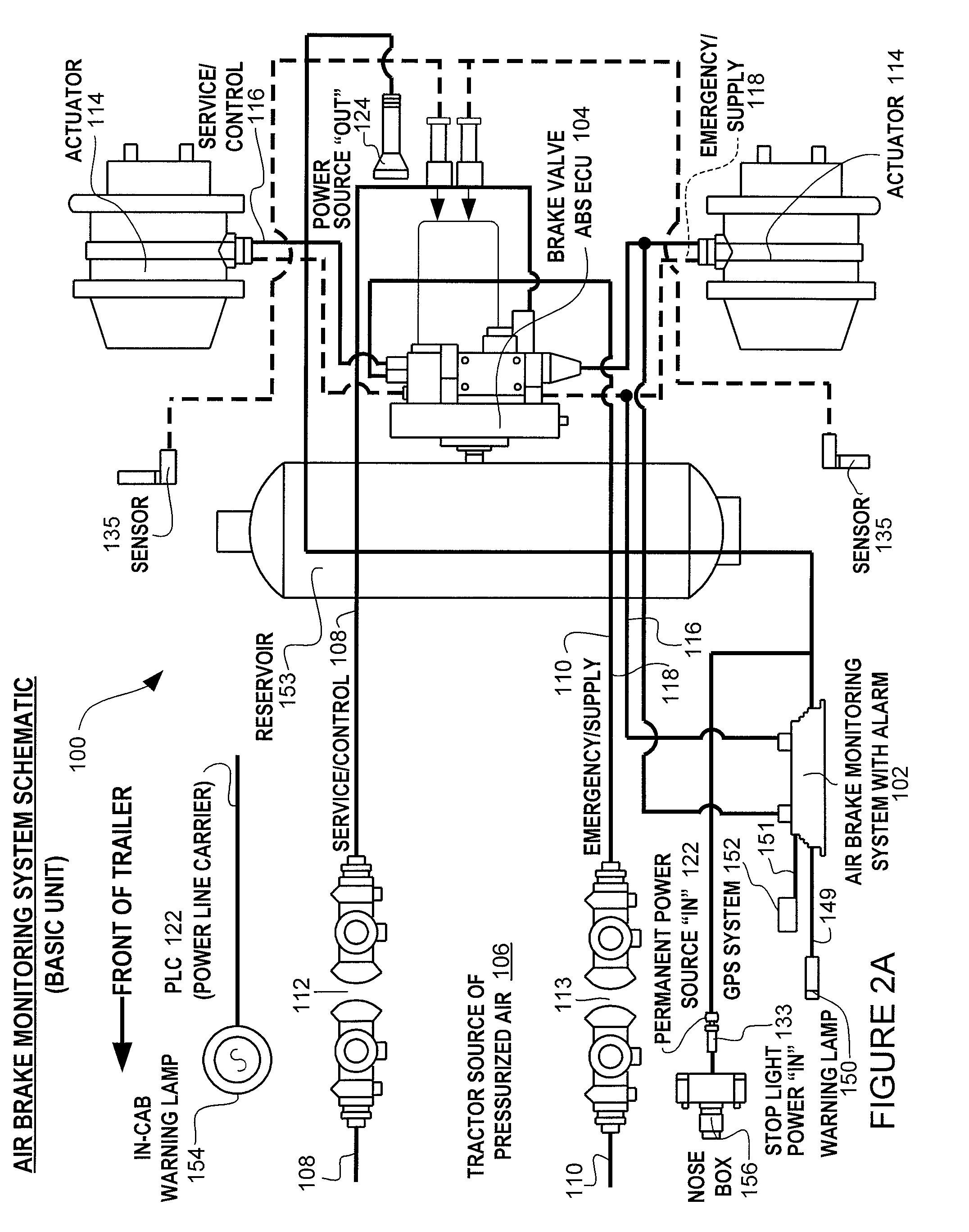
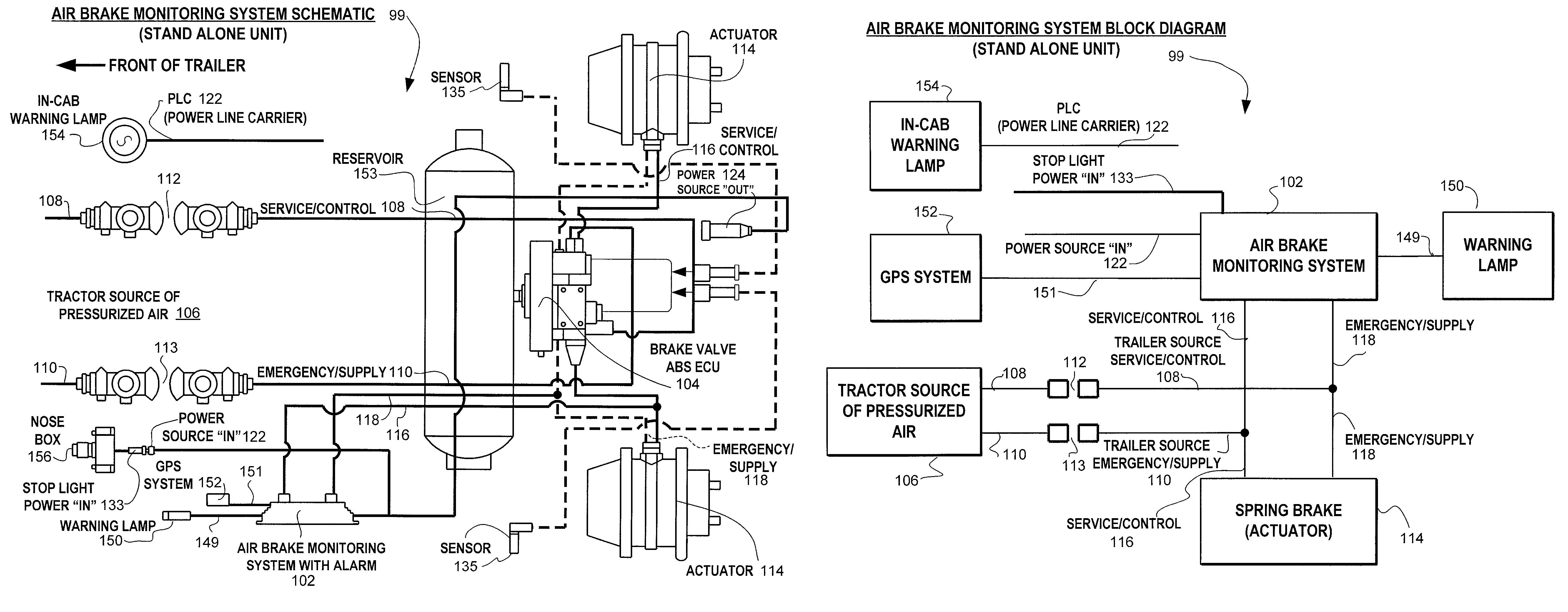
basic air brake system diagram
1. Power Pins: The power pins are responsible for delivering electrical power from the tow vehicle to the trailer. There are three power pins in a 7-way semi trailer plug, each corresponding to a specific voltage level - 12 volts, ground, and brake power.
Wabco Abs Wiring Diagram Wiring Diagram
2S/1M - 4S/2M PLC Select Anti-Lock Braking Systems (L30041) haldex.com PLC Select 1M -FFABS PLC Select 2M -FFABS INSTALLATION/SERVICE GUIDE 2-Port ABS

Haldex Trailer Abs Wiring Diagram
Summary of Contents for WABCO Easy-Stop Basic. Page 1 EASY-STOP™ TRAILER ABS: 2S/1M (BASIC AND STANDARD), 2S/2M, 4S/2M AND 4S/3M SYSTEMS MAINTENANCE MANUAL. Page 2 Failure to use special tools when required can cause serious personal injury to service personnel, as well as damage equipment and components. WABCO uses the following notations.

Wabco Trailer Abs Wiring Diagram
General Information The Haldex 2S/1M PLC Select ABS WNC Replacement Kit, part number AQ960514, is designed to replace or upgrade to PLC Technology on all WNC Trailer systems. The kit includes all components required to replace the WNC ABS Systems MBS1 and MBS1P. The WNC MBS2 requires AQ15457 axle hardware kit and the AQ960514 kit.
Wabco Trailer Abs Wiring Diagram keep going and going and wiring
The truth is the ABS lead, or ISO 7638 to give it it's proper title, is essential to making your trailer ABS function correctly. If you have the connections on your truck and trailer, they must be connected, and must be working correctly. You should also be looking at the ABS light in the cab, and not the one on the trailer headboard.
Meritor Wabco Trailer Abs Wiring Diagrams Manual EBooks Wabco
The ABS/EBS (Electronic Braking System) connectors for truck and trailer are used on nearly every commercial vehicle type with ABS/EBS System. They include various safety features: If a plug is incorrectly plugged in, it is automatically ejected by an ejector pin.